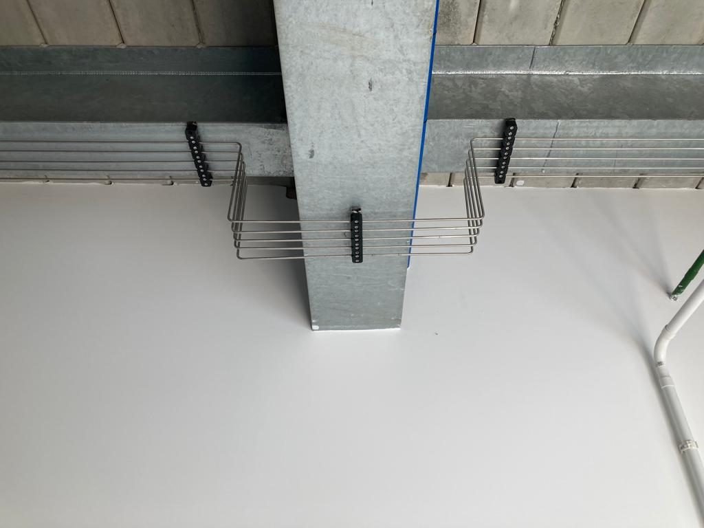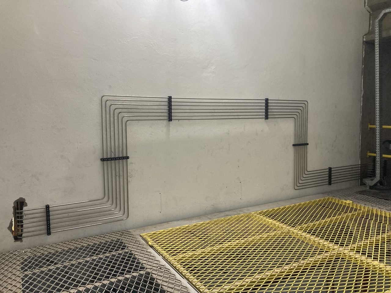
Pipe Clamps and Supports: Technical Fastening for Hydraulic, Pneumatic, and Gas Networks
Technical selection and application guide for modular pipe clamps (light, twin, heavy, and metal series according to DIN 3015) for fastening, organizing, and mechanically supporting industrial piping and gas networks.
Proper mechanical fastening and pipe support are essential for dimensional integrity, vibration damping, and operational safety in hydraulic, pneumatic, and specialty/industrial gas distribution networks. This technical guide covers modular pipe clamp families in polymers (PP and Polyamide 6) and metal alloys (aluminum, carbon steel, and stainless steel), detailing selection criteria, temperature limits, and recommended support spacing.
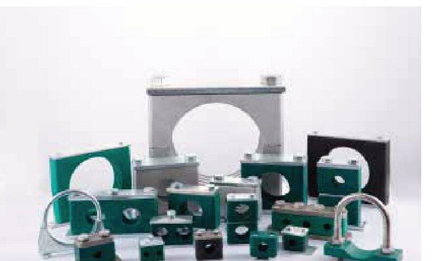
Modular Fastening and Support System
The product line combines two-piece clamp bodies in polymer or metal, cover plates, weldable or bolt-on bases, mounting rails, and stacking accessories for installing single, twin, or multi-line tubing runs in compact spaces.
1 | Main Product Families
| Family / Reference | Outer Diameter Range¹ | Characteristics and Application |
|---|---|---|
| Light Series • TLPG | 6 to 102 mm | Fastening of instrumentation and gas lines under standard mechanical loads; plate, rail, and stacking mounting options. |
| Twin Series • TTPG | 6 to 42 mm | Holds two parallel tubing lines; ideal for organized, compact routing. |
| Heavy Series • THPG | 8 to 406 mm | Reinforced configuration for higher mechanical demands; extended bolt and multi-position options. |
| Heavy Series with Elastic Insert | Model dependent | Reinforced body with internal rubber insert for vibration damping and shock absorption. |
| Metal Clamps • SKFGJ | Geometry dependent | Single, double, multi-line, flat steel, U-bolt, and anti-vibration models. |
| Special Supports • SKFA | Model dependent | Guide and anchor supports with two or more bolts, plus options for insulated lines. |
¹ Global diameter ranges per family as stated in the catalog. Exact availability depends on the dimensional group and selected configuration.
2 | Technical Differentiators
- Modular configuration: combines clamp jaws, cover plates, weld/bolt bases, and fasteners for diverse piping layouts.
- Flexible mounting: weldable or bolt-on plates, mounting rails for parallel multi-line runs, and multi-level stacked assemblies.
- Application-specific versions: twin, multi-line, elastomer-inserted, zinc-plated carbon steel, and stainless steel hardware upon specification.
- Selection by Outer Diameter (OD): ensures exact dimensional matching with metric (mm) and fractional/imperial (inch / Schedule) tubing and pipe.
3 | Clamp Body Materials and Temperature Reference Limits
| Body Material | Temperature Resistance Reference² | Application Notes |
|---|---|---|
| Polypropylene (PP) | −30 °C to +90 °C | Polymer option for standard operating conditions; catalog standard color is green. |
| Polyamide 6 (PA6) | −40 °C to +120 °C | Polymer option for broader thermal range and higher mechanical strength; black color (widely used in 316L stainless steel gas networks). |
| Aluminum | up to 300 °C | Metallic alternative for elevated temperatures; assembly limit must be confirmed per configuration. |
| Carbon / Stainless Steel | To be confirmed by drawing and grade | Available across multiple metallic series; zinc-plated finish for carbon steel and stainless steel for corrosive or cleanroom environments. |
² Reference values reproduced from the manufacturer catalog overview. They do not, in isolation, constitute certified operating limits for the complete mounted assembly.
4 | Installation Configurations and Best Practices
- Weldable or bolt-on base: prepare the supporting structure first, then position the bottom clamp half, the tube/pipe, the top clamp half, and the cover plate, tightening to the specified torque.
- Mounting rail: the rail is anchored to the structure and accepts rail nuts for fine lateral spacing of multiple parallel clamps.
- Stacked assembly: stacking bolts and locking plates allow multi-tier routing where tray or wall space is limited.
- Installation rule: never weld the base plate while the polymer clamp body is mounted. At changes of direction (90° bends), place supports close to both sides of the bend.
5 | Reference Support Spacing
| Line Outer Diameter (OD) | Recommended Span | Line Outer Diameter (OD) | Recommended Span |
|---|---|---|---|
| 6 – 14 mm | 0.9 m | 50 – 57 mm | 3.0 m |
| 15 – 22 mm | 1.2 m | 90 – 108 mm | 4.0 m |
| 30 – 38 mm | 2.0 m | 168.3 – 220 mm | 5.5 m |
| 40 – 48.3 mm | 2.5 m | 356 – 406 mm | 7.5 m |
Note: Final support spacing depends on tubing material, wall thickness, fluid weight, process loads, temperature, vibration, and thermal expansion. Do not use this table as a substitute for structural engineering calculations.
6 | Specification Checklist and Standards
- Tubing / Pipe: specify actual outer diameter (OD), material, number of parallel lines, and presence of insulation.
- Service conditions: specify temperature at the fastening point, vibration, thermal movement, and ambient corrosivity.
- Clamp configuration: define series (Light TLPG, Twin TTPG, Heavy THPG, or Metal), body material (PP, PA6, Aluminum, Stainless Steel), smooth or ribbed bore, base/rail type, and single, twin, or stacked mounting.
- Standards Reference: The catalog references DIN 3015 for tightening torques and axial holding forces on applicable series, as well as metallic clamp standards such as DIN 3567, JB/ZQ, and HG/T 21629.
Request Information
Our technical team is ready to serve your demand.
Technical Gallery