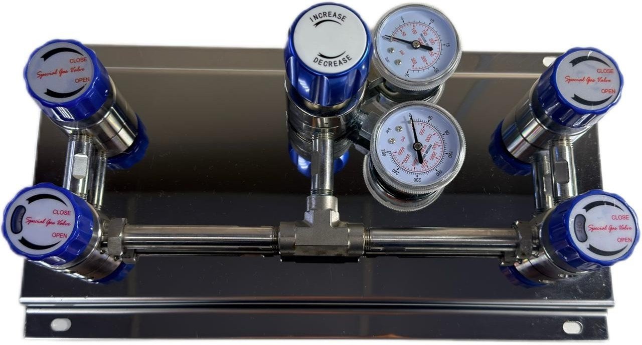
Technical checklist for central gas supply systems: key manifold inspection points
Review good practices for inspecting central gas supply systems and manifolds, including key checks for pressure regulators and connections.
Manifolds, distribution headers, and pressurized gas networks require periodic technical attention to mitigate the risk of operational interruptions and process deviations. Visual and structural assessment of supply lines should consider the mechanical specifications of each installation, the component manufacturers’ stated limits, and the applicable regulatory framework. This article presents good practices for the preliminary and preventive assessment of central gas supply systems, focusing on regulator stability, flexible-connection maintenance, and inspection responsibilities under the applicable requirements.
Operational integrity: beyond continuous gas flow
In industrial utility engineering, continuous pressure at the point of use should not be treated as the sole indicator of a central gas supply system’s integrity. Manifold and pressure-regulator systems may remain operationally stable even when early-stage wear is present.
Low-rate leakage at connections, mechanical fatigue at metal interfaces, and solid residue in supply lines are anomalies that may precede incidents or unplanned shutdowns. Pressurized-system reliability depends on systematic checks of component condition, traceable technical documentation, and material compatibility with the gas service. An assessment should therefore not rely solely on the immediate presence of flow.
Design variables: gases and operating conditions
The mechanical design of a central distribution system is sized according to the physicochemical properties of each gas and the process pressures. Material selection and the specification of active or passive safety systems should follow application-specific engineering criteria:
- Flammable gases: Systems handling combustible fluids require hazardous-area classification studies to define risk zones. Electrical equipment installed near the enclosure should be compatible with the area classification established by the design and use protection techniques appropriate to each zone—such as intrinsic safety or increased safety—rather than relying on explosion-proof enclosures as the sole safety criterion.
- Oxidizing gases, such as oxygen: These systems require rigorously cleaned materials free from oils, greases, and other organic compounds. Hydrocarbon contamination can promote rapid oxidation; components in contact with the gas should therefore be identified by the manufacturer as suitable for oxygen service.
- Corrosive and toxic gases: These services require metallic materials with suitable chemical resistance and, when specified by the design or risk assessment, auxiliary purge and inerting circuits before connections are replaced or opened.
- Inert gases: Although chemically stable, asphyxiant-gas leakage in a confined space reduces the local oxygen concentration. Physical containment and ventilation requirements should be assessed against the stored volume, enclosure dimensions, and the requirements applicable to the installation.
Inspection points for distribution manifolds
Visual inspection of manifolds and headers should focus on components exposed to greater mechanical stress or pressure variation.
Isolation, check, and relief valves
Shutoff valves should provide leak-tight isolation when operated, as specified by the installation design. Check valves are recommended on manifold branches serving multiple cylinders to prevent accidental reverse flow between vessels at different pressures.
Pressure-relief devices—such as safety valves or rupture discs—should, when included in the design, be set so their opening pressure does not exceed the piping system’s maximum design pressure. Discharge should be routed to a safe outdoor location when required by the risk assessment or applicable regulations.
Pressure-regulating devices
A pressure regulator’s dynamic behavior provides information about the condition of its seats and diaphragms.
- Droop: The reduction in outlet pressure as flow increases is a common physical characteristic of spring-loaded direct-acting regulators—as described in Swagelok technical bulletin MS-02-492—and does not, by itself, indicate a mechanical failure.
- Downstream pressure increase (creep): A continuous rise in outlet pressure above the set point when there is no demand indicates leakage past the regulator seat, which may result from particles or seal wear. The condition requires assessment and maintenance or replacement in accordance with the manufacturer’s instructions.
- Diaphragm materials: The selection of an elastomeric or metallic diaphragm depends on allowable gas permeation and the process-purity requirements defined by the design.
- Pressure gauges: Gauges should have a safety window or rear blowout device when specified by the design and should be included in the installation’s periodic calibration program.
Flexible connections and joining components
Flexible connections undergo cyclic mechanical stress as supply vessels are replaced. Steel restraint cables can contain hose whip if a high-pressure connection separates; whether this measure is required should be established by the installation risk assessment.
High-pressure regulators and manifolds should be pressurized slowly and gradually, as recommended in gas-supplier guidance such as Air Products Safetygram-12, to avoid pressure shock at regulator seats and other safety hazards.
Components from different manufacturers should not be mixed in double-ferrule compression tube fittings. As stated in manufacturer instructions such as Swagelok manual MS-12-01, combining components from different sources can compromise the joint’s sealing geometry and cause leakage. Always follow the assembly instructions issued by the manufacturer of the fitting system installed.
Enclosure infrastructure and physical installation
The location of a central gas supply system should support the mechanical stability of the cylinders and the safe dispersion of potential leakage:
- Cylinder restraint: When specified by the design, supply vessels should remain upright and be individually secured with chains, clamps, or structural supports designed to withstand their weight and prevent tipping.
- Contents identification: The fluid handled by fixed manifolds should be clearly and legibly identified in accordance with the procedures and regulations applicable to the installation.
- Ventilation and monitoring: Industrial-gas enclosures should have permanent natural or mechanical ventilation, together with active monitoring or gas detection when required by the risk assessment or applicable regulations.
Engineering documentation and regulatory framework (NR-13)
The technical integrity of pressurized systems also depends on consistent documentation. Maintaining a technical file proportionate to the project and applicable requirements is recommended; it may include current as-built schematics and material specifications. This file should not be confused with the mandatory safety record required for boilers or pressure vessels falling within the scope of Brazil’s NR-13 regulation.
NR-13 guidance: scope of application
Under Brazil’s NR-13 regulation—approved by MTP Ordinance No. 1,846/2022 and updated in 2023—the piping provisions apply to piping systems connected to boilers or pressure vessels that themselves fall within the regulation’s scope.
Transportable vessels and portable containers for compressed fluids, such as mobile commercial gas cylinders, are excluded from NR-13 classification and mandatory inspection under item 13.2.2(a). However, a cylinder supply system should not be assumed to be excluded without a technical assessment of any connection to other plant equipment that may fall within NR-13, such as fixed receiver vessels.
In addition, item 13.2.3 states that exclusion from NR-13 does not release the employer from the duty to inspect and maintain the relevant equipment and systems in safe operating condition. Such work must be performed or overseen by a responsible technical professional and follow manufacturer recommendations, design codes, and applicable standards.
For installations formally within the scope of NR-13, the definition of a legally qualified professional (Profissional Legalmente Habilitado—PLH) under item 13.3.2 and the coordination of safety inspections under item 13.3.3 must comply with the professional regulations and legal responsibilities established by the relevant professional councils.
Preliminary operational-criticality screening
The following table presents a qualitative criticality screen based on observable mechanical scenarios to support maintenance planning for central gas supply systems:
| Installation scenario | Physical signs of deviation | Recommended technical action |
|---|---|---|
| Flammable gases in an enclosure with restricted ventilation and electrical equipment whose compatibility with the area classification has not been demonstrated. | Wear on the outer braid of high-pressure flexible connections or geometric misalignment at compression fittings. | Stop unplanned intervention and refer the condition for assessment by qualified personnel under the facility’s safety procedure. |
| Inert or high-purity gases in ventilated outdoor enclosures. | Solid deposits or contaminants accumulated in pressure-regulator inlet filters. | Stop unplanned intervention and refer the condition for assessment by qualified personnel under the facility’s safety procedure. |
| Metal cylinder supports exposed to the weather and showing visible oxidation. | Surface corrosion at metal bases requiring assessment of section loss, stability, and vessel-retention capacity. | Stop unplanned intervention and refer the condition for assessment by qualified personnel under the facility’s safety procedure. |
Safety note: any gas leak should be assessed immediately by qualified personnel under the facility’s specific safety procedures and with due consideration of the fluid’s chemical properties.
Common installation and operating errors
- Instant pressurization: Abruptly opening high-pressure cylinder valves creates mechanical pressure shock at the regulator seat and may reduce the service life of internal seals and sensitive diaphragms.
- Incorrect sealing geometry: Mixing ferrules and compression-fitting bodies from different manufacturers can create microleak paths at the metal interface because of incompatible assembly tolerances.
- Ignoring the source of contamination: Repeatedly replacing or cleaning inlet filters saturated with oxide residue without investigating the root cause of upstream contamination in the piping or supplied vessels.
Frequently asked questions
Does NR-13 apply to every industrial central gas supply system?
Not automatically. NR-13 covers only piping systems connected to boilers or pressure vessels that fall within the regulation’s own scope. Systems supplied by standard transportable cylinders are excluded from its direct administrative requirements under item 13.2.2(a). However, if the network is physically connected to covered equipment—such as stationary cryogenic tanks or receiver vessels—the interconnecting piping should be assessed. The final determination of regulatory applicability must be confirmed by a legally qualified professional (PLH).
What does NR-13 item 13.2.3 say about systems outside its scope?
Item 13.2.3 states that exclusion from the regulation does not remove the employer’s duty to conduct structural inspections and preventive maintenance on pressurized systems that may present risks to workers. Such activities must be performed or overseen by a qualified technical professional and take account of manufacturer manuals, design codes, and current technical standards.
How are the specific requirements for flexible connections and fittings determined?
High-pressure flexible connections should be specified and maintained in accordance with the pressure, cycle-life, and chemical-compatibility limits stated by their manufacturers. Healthcare facilities must observe the specific requirements applicable to medical-gas hose assemblies, while industrial protection measures should be based on a detailed assessment of the installation’s operational risks.
Request Information
Our technical team is ready to serve your demand.

Technical Gallery